

LED Chaser AddiKit
$10.10
Unit price /
Unavailable
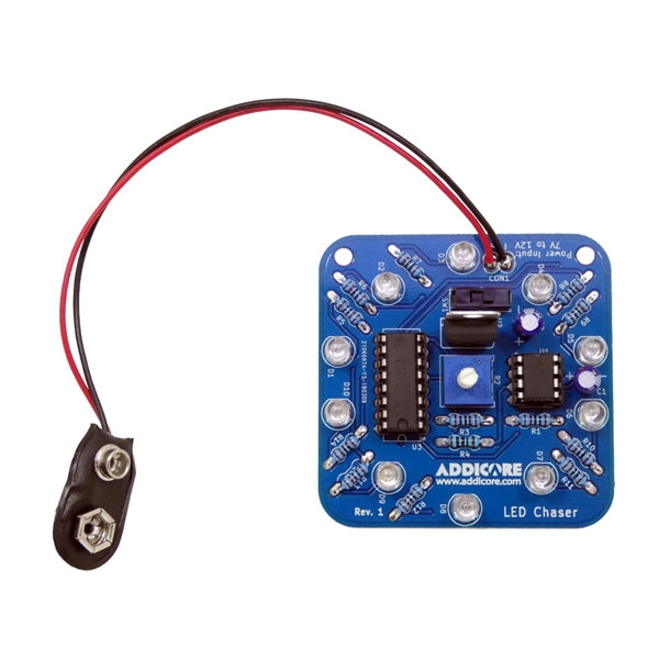
Introducing the Addicore LED Chaser AddiKit! By adjusting the resistance of the trim pot the signal from the 555 timer will change causing the decade counter to speed up or slow down.
This AddiKit is great for beginning or intermediate solder practice.
Addicore also offers this kit for education and events. Email us at sales@addicore.com for more information.
Note: This is a self-assembly electronics kit which requires soldering. 9V Battery not included.
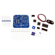
AddiKit Contents
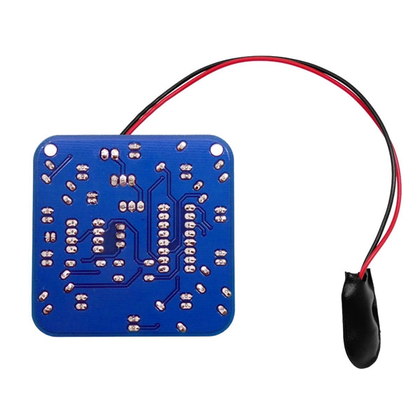
- 1 - LED Chaser Printed Circuit Board
- 2 - 10uF Capacitors
- 1 - 9V Battery Cable (Battery not included)
- 10 - LEDs (Color Selectable Above)
- 12 - 1K Ohm Resistors
- 1 - 100 Ohm Resistor
- 1 - 10K Potentiometer
- 1 - Switch
- 1 - CD74HC4017E Decade Counter
- 1 - 555 Timer
- 1 - L7805CV 5V Regulator
- 1 - 8 Pin DIP Socket
- 1 - 16 Pin DIP Socket
Instructions
- Install and Solder one 100-ohm (brown-black-black-black-brown) resistor at R4
- Install and Solder twelve 1K ohm (brown-black-black-brown-brown) resistors at R1, R3, R5, R6, R7, R8, R9, R10, R11, R12, R13, R14
- Install and Solder the switch at SW1
- Install and Solder the 7805 voltage regulator at U2. The flat metal side of the component should be facing the switch
- Install and Solder the 10K potentiometer at R2
- Install and Solder the 10uF capacitors at C1 and C2. Make sure that the negative stripe on the component matches the negative mark on the board
- Install and Solder the 8 pin IC socket at U1. Make sure that the pin one notch in the part matches up with the pin one mark on the board
- Install and Solder the 16 pin IC socket at U3. Make sure that the pin one notch in the part matches up with the pin one mark on the board
- Install and Solder ten LEDs at D1, D2, D3, D4, D5, D6, D7, D8, D9, D10. Make sure that the flat side of the LED (cathode) matches up with the flat side of the component outline on the board
- If you would like to power the LED Chaser using a 9V battery, then install and solder the 9V battery cable at CON1. Match the black wire with the negative symbol on the board (-) and the red wire with the positive symbol on the board (+). The board can also use any other 7V to 12V power source.
- Install the 555 timer into the socket at U1 and the Decade Counter (CD74HC4017E) into the socket at U3. Make sure that the notch in each chip is aligned with the notch in the IC socket. You may need to bend the leads of the chips in sightly before it can be pressed in.
- Power the board and turn the switch on to light up the LEDs. Turn the knob on the potentiometer to speed up or slow down the chasing LEDs.